1. Type of thread
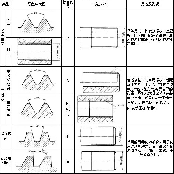
According to the use, the thread can be divided into two types: joint thread and drive thread. See Table 1 for the types and uses of commonly used standard threads.

Table 1
2. The drawing method of threaded joint
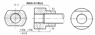
As shown in the cross-sectional view, the inner and outer threaded joints are drawn by external threads, and the rest are still represented by their respective drawings. The thick and thin solid lines of the inner and outer threads should be aligned separately.

3. Thread code labeling
The thread on the drawing needs to be marked with the specified thread code. Except for the pipe thread, the thread code is marked in the following format:

The labeling format of the pipe thread is: feature code size code rotation
Among them, the right-handed thread is omitted and the left-handed is indicated by "LH".
4. Marking of thread marks
When the thread precision requirements are high, in addition to the thread code, the thread tolerance tape code and the thread screw length should be marked.
The labeling format of the thread mark is: thread code - thread tolerance band code (medium diameter, top diameter) - screw length
Instructions for labeling content :
(1) The tolerance band code is represented by a number plus a letter (the upper thread is used for upper thread and the lower thread is used for external thread), such as 7H, 6g, etc., it should be specially pointed out that 7H, 6g, etc. represent the thread tolerance, and H7, g6 represent the cylinder. Tolerance code.
(2) The screw length is defined as three types: short (indicated by S), medium (indicated by N), and long (indicated by L). In general, the threaded length is not marked and the thread tolerance band is determined by the medium twist length (N). If necessary, add the screw length code S or L, such as "M20-5g6g-L". For special needs, indicate the value of the length of the screw, such as "M20-5g6g-30".
5. The marking method of the thread mark on the view
As shown in the legend in Table 1, except for the pipe thread, the marking of the thread mark on the view is the same as the method of linear dimensioning; while the pipe thread is in the form of a leader line, the leader line should be drawn from the large diameter and should not be parallel to the section line. .
Descriptions marked in Table 1 :
(1) M16-5g6g means coarse thread common thread, nominal diameter 16, right-handed, thread tolerance with medium diameter 5g, large diameter 6g, and the screw length is considered by medium length.
(2) M16×1LH-6G means ordinary thread of fine teeth, nominal diameter 16, pitch 1, left-handed, thread tolerance, medium diameter and large diameter are both 6G, and the screwing length is considered as medium length.
(3) G1 means the inch non-thread sealing pipe thread, size code 1in, right-handed.
(4) Rc12 means the inch threaded taper pipe thread, size code 12in, right-handed.
(5) Tr20×8 (P4) indicates trapezoidal thread, nominal diameter 20, double line, lead 8, pitch 4, right-handed.
(6) B20 × 2LH means serrated thread, nominal diameter 20, single wire, pitch 2, left-handed.