Our company designs and manufactures a semi-continuous casting machine for aluminum alloy casting for a certain unit, which requires a casting weight of 5kN and a casting length of 2m. Mainly referring to the design of the casting machine produced in the former Soviet Union, the design defects in the original casting machine were improved in the design, and good use results were obtained.
1. Improvement of the lifting nut
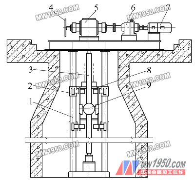
The screw type semi-continuous casting machine is mainly composed of a transmission system and a casting machine body. The casting machine body mainly includes a driving screw, a casting platform and a lifting nut (see Fig. 1). The transmission system transmits the power to the lead screw, and the lifting nut rotates with the lead screw to drive the casting platform to move up and down. During the work, the lifting nut and the screw rod bear the full weight of the casting platform and the ingot. Therefore, the rationality of the structure of the lifting nut directly affects the performance of the entire casting machine. We have made the following improvements to the structure of the lifting nut of the original casting machine, which greatly improved the service life of the nut.

figure 1
1. Guide post 2. Guide slide 3. Drive screw 4. Handwheel 5. Steering gear
6. Reducer 7. Motor 8. Casting platform 9. Lifting nut
(1) Defects in the original design structure
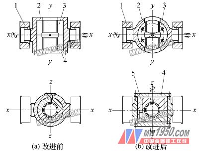
Figure 2a is a structural view of the original casting machine lift nut. As can be seen from the figure, the original design nut only moves left and right along the x-axis and two degrees of freedom around the x-axis. Due to the machining, installation and other errors of the lead screw, it is difficult to ensure the straightness of the lead screw. Therefore, the lifting nut often wears on the lead screw, which causes the nut to wear faster.
(2) Improved structure
Figure 2b shows the improved lift nut structure. The two split nuts are integrally joined by four screws, and the outer shape is cylindrical and installed in the sleeve. There is a gap between the sleeve and the nut, so that the nut can rotate in the sleeve and move along the z-axis; and the sleeve can also move in the x-axis direction and can rotate around the x-axis. In this way, multiple directions can be compensated, so that no jamming phenomenon occurs between the lifting nut and the lead screw during operation, so that the casting platform can be lifted freely, thereby prolonging the service life of the lifting nut.

figure 2
1. nut holder 2. sleeve 3. split nut 4. end cover 5. coupling screw
Next page